Small Pixel IR Sensors: Optimizing SWaP-C and Performance
Key Definitions
| Focal Plane Array (FPA) | A two-dimensional array of light detectors that is placed in the focal plane of an optical system |
| Focal Length or Effective Focal Length (EFL) | The distance between the center of a lens and its focus |
| Field of View (FOV) | The angular maximum area of a scene that a lens can see |
| Instantaneous Field of View (IFOV) |
The smallest detail within the FOV that can be detected or seen at a set distance |
| f-number (f/#) | A measure of the light-gathering ability of an optical system calculated by dividing the focal length by the diameter of the entrance pupil |
| Spatial Resolution | The physical dimension in a scene that represents one pixel of an image |
| Blur Spot | An optical spot caused by a cone of light rays from a lens not coming to a perfect focus when imaging a point source (also known as Circle of Confusion (CoC), Disk of Confusion, Circle of Indistinctness, or Blur Circle) |
| Diffraction-Limited Optics |
The principal limit to an optical system’s resolution caused by the physics of diffraction where diffraction-limited optics have reached this limit of resolution performance |
Background
Innovation has driven a decrease in IR pixel pitch, enabling the potential reduction in size, weight, power, and cost (SWaP-C) of infrared (IR) thermal camera modules. SWaP-C optimization of smaller pixel-pitch IR camera modules — or “cores” with fixed field of view (FOV) lenses — has led to new products, new markets, and new missions where thermal cameras enhance efficiency, provide awareness, and save lives. This may not always apply to more complicated, long-range IR systems where the impact of pixel pitch on size, weight, cost, and performance for both a continuous zoom (CZ) lens and the complete MWIR system is not straightforward. These scenarios require tradeoff analysis at the component and system level.
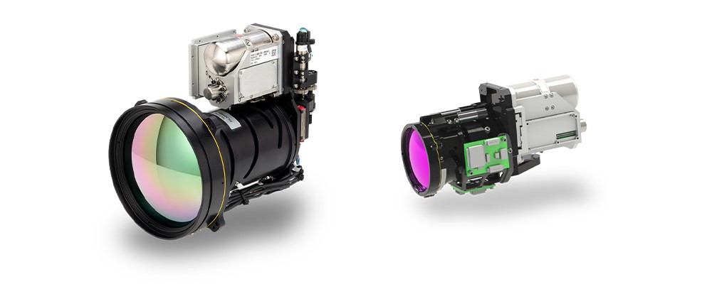
Figure 1. 8 µm MWIR Neutrino SX8 - CZF 30-300 (left) and 15 µm MWIR Neutrino LC - CZ 27-275 (right)
From ROICs, detectors, and cryocoolers to mid-wave IR (MWIR) and long-wave IR (LWIR) thermal camera modules and CZ optics, Teledyne FLIR is the world’s only vertically integrated infrared (IR) hardware and perception stack provider. Teledyne FLIR designs and manufactures infrared IR camera sensors and the associated optics in high volumes, selling complete integrated imaging camera modules with all components designed to optimize system SWaP-C and performance. For example, the Neutrino IS series, shown in Figure 1, includes multiple MWIR pixel pitches and CZ lens options. This vertical integration provides Teledyne FLIR with a unique perspective on the relationship between component specifications and IR system optimization.
Optical Design SWaP-C
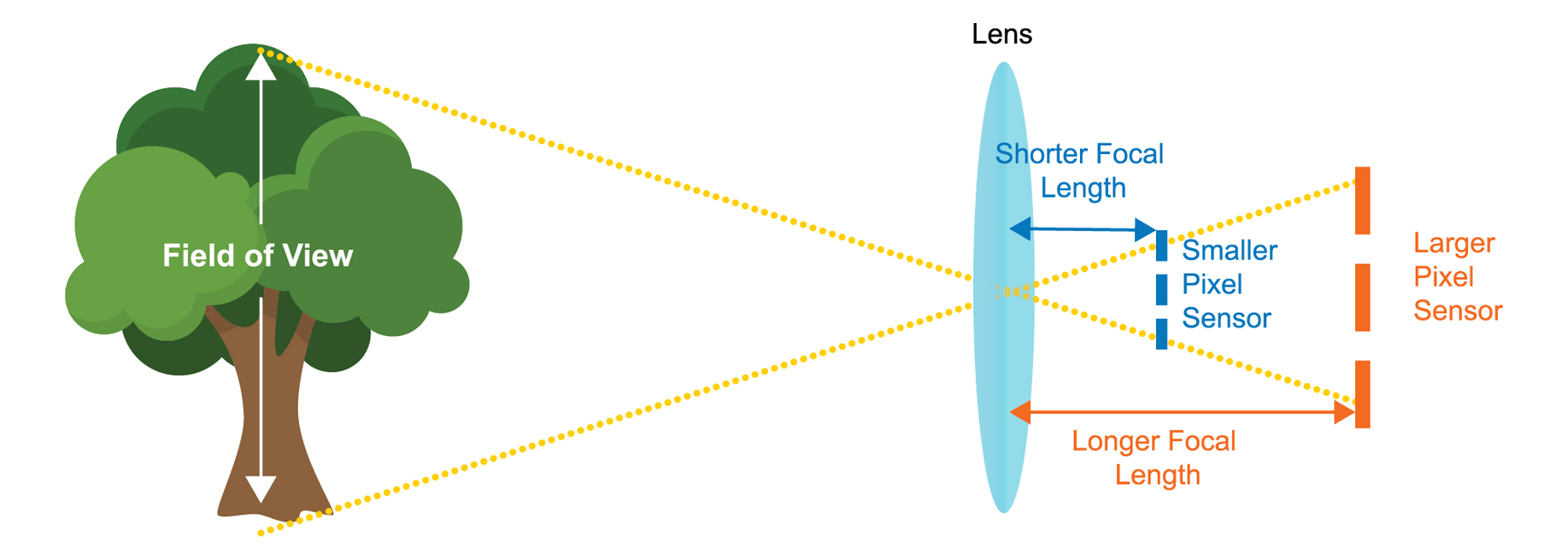
FIGURE 2. REDUCING PIXEL PITCH REDUCES FOCAL LENGTH AND ARRAY SIZE FOR A GIVEN FOV AND RESOLUTION
Figure 2 illustrates that for a given number of pixels on target, pixel resolution, and field of view (FOV), shrinking pixel pitch can theoretically reduce system size. Pixel array size and the Effective Focal Length (EFL) are reduced proportionally for a given resolution. However, when developing MWIR systems that include CZ lenses, there are additional factors to consider that diminish or may even overcome the theoretical pixel pitch reduction benefit. Integrators must optimize the complete system performance, design complication, cost, and size when CZ lenses dominate many of the SWaP-C metrics.
Sensitivity
Smaller pixels require a proportionally faster f-number to achieve similar sensitivity due to pixel size, a general reduction in quantum efficiency, an increase in dark current, and an increase in fixed pattern noise. This means the system diameter (Ø), which is driven by the front optical element or entrance aperture, is the same as or slightly larger than larger-pixel systems of the same sensitivity.
Spatial Resolution
Smaller pixels also require a faster f-number to achieve the same spatial resolution, i.e., pixels per blur spot, assuming diffraction-limited optics. f-numbers lower than ƒ/3 are notably more expensive and difficult to manufacture, as optical aberrations must be controlled over a larger angle; therefore, near-diffraction-limited performance is prohibitively costly and/or unachievable.
Optical Tolerance
Faster f-numbers require tighter optical design tolerances, complicating the design and possibly requiring additional lens elements to achieve similar performance; this extends the length of the shorter EFL lens assembly longer than the slower f-number assembly used by a larger-pixel system. Size, weight, and cost are all negatively impacted.
Dynamic Range
Smaller pixels have a reduction in dynamic range; capacity generally reduces with pixel pitch, which reduces system performance.
Pixel-to-Pixel Crosstalk
Pixel-to-pixel crosstalk becomes more difficult to mitigate as the pitch-to-diffusion-length ratio decreases and fabrication processes become more challenging. This crosstalk further degrades system modulation transfer function (MTF) and overall performance.
The advantages of small pixel pitches are more straightforward when designing fixed FOV lens systems, but as the example illustrates, smaller pixel pitch does not necessarily translate to significant SWaP-C advantages for IR systems that include a CZ lens. Table 1 provides a real-world example comparing three system designs derived from the specification of typical 10x CZ lenses where spatial resolution (IFOV) is held equal. The MWIR pixel pitch drives f-number requirements, which impacts the number of optical elements and the design of the optical system. Size, weight, and cost of CZ optics increase as pixel pitch decreases from 15 µm to 8 µm to 5 µm.
TABLE 1. SPECIFICATION OF TYPICAL 10X CZ LENS FOR 5 µm, 8 µm, AND 15 µm PIXEL PITCH SENSORS
|
PIXEL PITCH |
5 µm |
8 µm |
15 µm |
COMMENTS |
|
f-number |
1.8 |
2.9 |
5.5 |
Equivalent sampling and sensitivity |
|
EFL |
100 mm |
160 mm |
300 mm |
Equivalent IFOV |
|
Optical Elements |
~10 |
~9 |
~8 |
Faster f-number requires more optical elements |
|
Optics System Dimensions |
Ø = 58 mm L = ~130 mm |
Ø = 58 mm L = ~130 mm |
Ø = 58 mm L = ~100 mm |
Length (L) can be notably shorter than EFL for slower f-numbers or longer than EFL for faster f-numbers |
|
Optics Weight |
>100 g |
~70 g |
~40 g |
Faster f-number increases weight due to number, size, thickness, and curvature of optical elements |
|
Optics Cost |
~1.8x Cost |
~1.5x Cost |
Cost |
Faster f-number increases cost due to number, size, thickness, and curvature of elements, and manufacturing processes, e.g., alignment complexity |
Infrared System Cost
The IR system-level cost includes the optics cost noted in Table 1 and the camera module cost, which includes the die, wafer, cryocooler, and other subcomponent cost inputs. As shown in Figure 3, the system level cost decreases with pixel pitch, reaching the minimum for the example MWIR with a 10x CZ lens at 8 µm where the camera module cost is minimized. The 8 µm pixel pitch provides 9% and 19% system-level cost savings when compared to the 5 µm and the 15 µm pixel pitches, respectively. In simplest terms, system-level costs hit a point of diminishing returns and become more costly as the smallest pixel sensors are utilized.
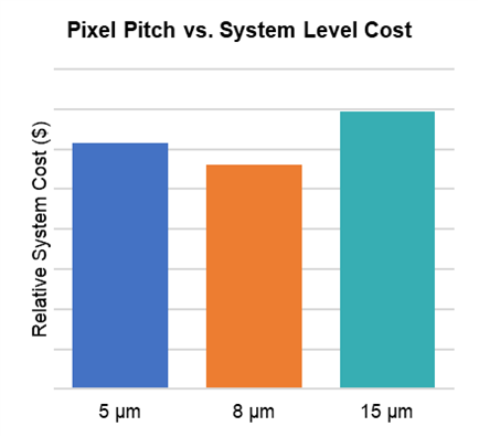
FIGURE 3. EXAMPLE MWIR WITH 10X CZ LENS SYSTEM-LEVEL COST MINIMIZED AT 8 µM
Infrared System DRI Performance
In addition to the cost, size, and weight advantage, larger pixel pitch systems can also have detection, recognition, and identification (DRI) performance advantages. DRI are criteria describing the effective range of a thermal camera. Teledyne FLIR uses DRI probabilities modeled using NV-IPM, an industry-standard passive sensor modeling tool. V50, the measured task difficulty, is the targeting task performance (TTP) metric value required to provide the user with a 50 percent probability of accomplishing a given task. These criteria give a 50% probability of an observer discriminating an object to a detection, recognition, and identification level.
Identification (ID)
For the identification task, the observer must correctly identify each target from the target set.
Recognition (Rec)
For the recognition task, the observer must correctly identify the correct class of the target such as Tracked/Wheeled-Armored/Wheeled-Soft (Military Vehicles) or Weapon/Non-Weapon (Two-Handheld Objects).
Detection (Det)
For the detection task, the observer must correctly detect the target in a scene. Continuing the 10x CZ lens design example, the performance of the three systems can be modeled using a target critical dimension of 3.1 m and a target temperature variation of 4.0 K in the NV-IPM model. Also consider a typical degradation in Optical Aberration MTF for an f/1.8, f/2.9, and f/5.5 optic, a conservative reduction in signal-to-noise for 5 µm, 8 µm, and 15 µm pixel pitch holding the Detector Diffusion MTF constant and keeping all other parameters equivalent, e.g., target, atmosphere, camera spectral transmission, display, etc.
The distances at which there is a 50% probability of achieving the task for the V50 measured task difficulties of 2.0 (detection), 9.0 (recognition), and 13.0 (identification) are provided in Table 3. The modeled data indicates that the 15 µm pixel pitch system has distance advantages of 12% for detection, 10% for recognition, and up to 12% for identification when compared with the 5 µm pixel pitch.
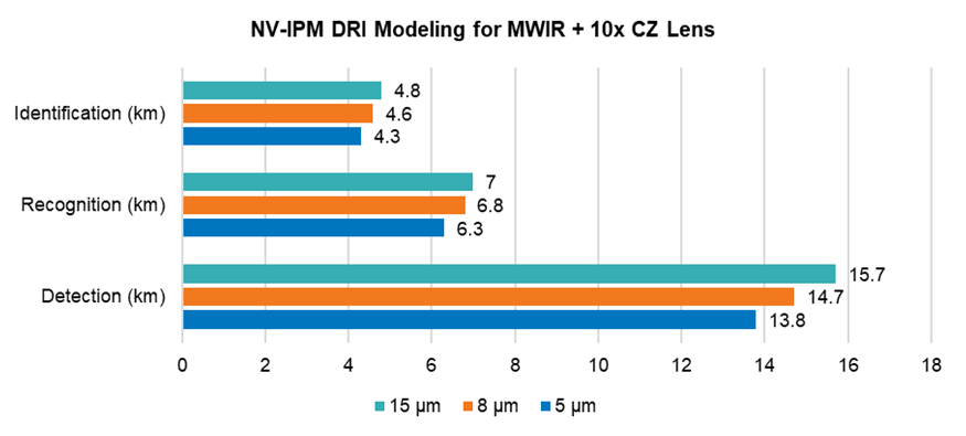
FIGURE 4. NV-IPM DRI MODELING FOR MWIR WITH 10X CZ LENS FOR 5, 8, AND 15 µM PIXEL PITCH
Small Pixel Pitch Design Tradeoff Summary
When CZ lens cost and IR system-level cost and performance are examined for 5 µm, 8 µm, and 15 µm pixel pitch systems, SWaP-C and performance are not optimized by pixel pitch minimization. Smaller pixels typically require a faster f-number, which increases the optic’s complexity, size, weight, and cost. The IR camera module cost, which includes the wafer, cryocooler, and other subcomponents, is also not minimized with smaller pixels. As shown in the example, the IR system-level cost is minimized at 8 µm, not at the smallest 5 µm pixel pitch. When the comparison example is extended to include performance, the largest pixel system of 15 µm is shown to have superior DRI distances. In summary, integrators and users will find that the push for ever smaller pixels reaches a point of diminishing returns for key system requirements including SWaP-C and performance.
Please refer to https://www.flir.com/oem for more information.
Related Articles
-
 Whitepaper
Deploying AI Object Detection, Target Tracking and Computational Imaging Algorithms on Embedded Processors
Learn more -
 Fundamentals
Simplify MWIR Development with Neutrino Featuring InVeo Electronics
Learn more -
 Whitepaper
Understanding Cryocooled System Reliability
Learn more